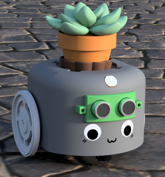
Render of CAD concept in Fusion 360.
I did all of the CAD work in Autodesk Fusion 360, which included modelling the existing parts (wheels, motors, etc.) and the custom parts to be manufactured through laser cutting and 3D printing. As we wanted this robot to look like a sellable product, we chose to enclose all of the circuitry with an appealing casing.
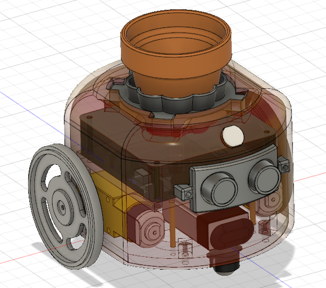
Front of assembly.
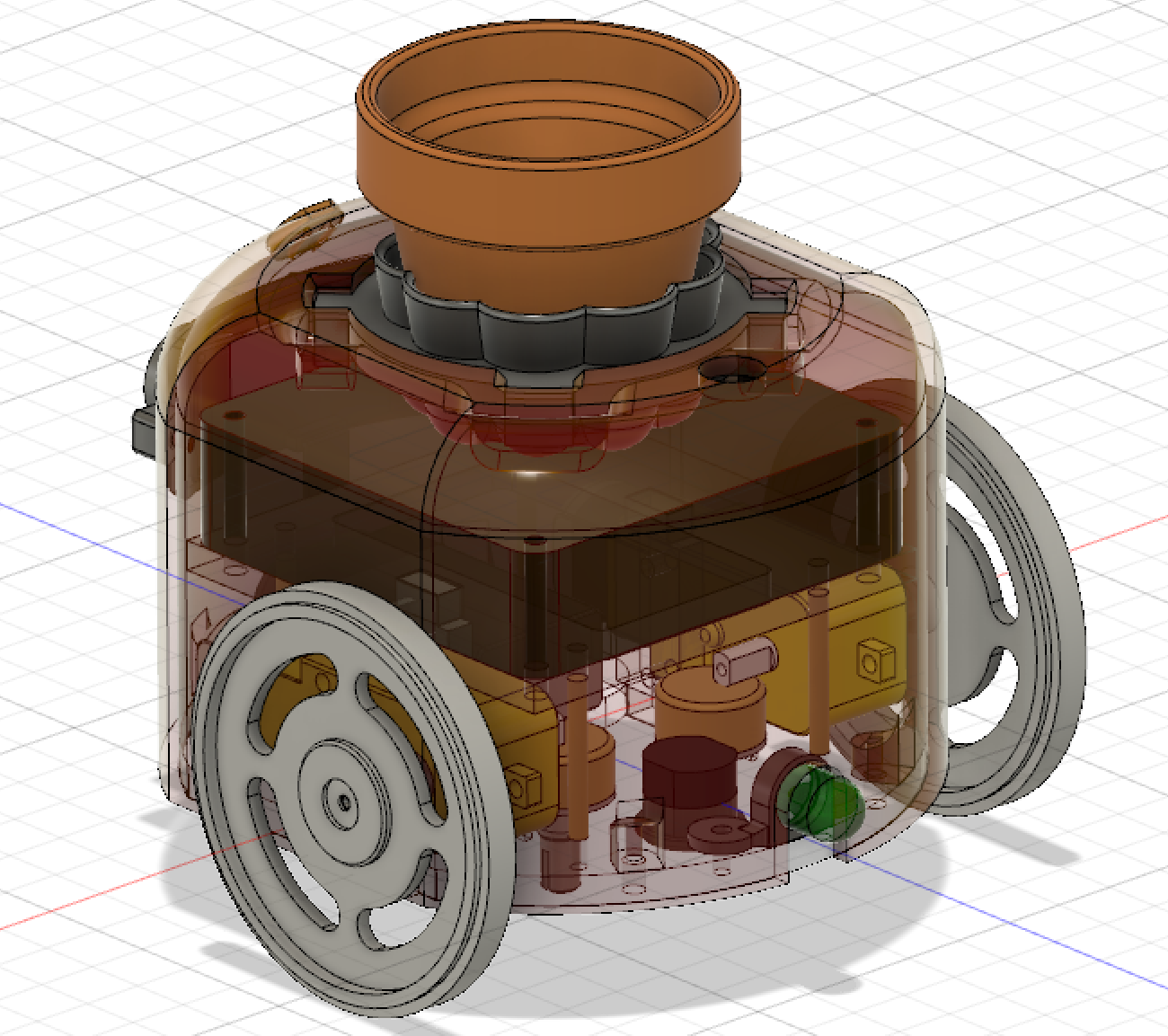
Back of assembly.
The assembly consists mainly of a 3D printed outer case and two internal acrylic plates as seen in the above two images. The 3D printed casing (shown in a transparent red material) encloses the entire robot while leaving mounting points for an ultrasonic sensor, photoresistor, and plant pot. Notches were included for the wheels and LED so they could mounted onto the internal structure before attaching the casing on top. The large brown block seen inside the assembly is a placeholder for the final PCB to ensure there was enough room for components.
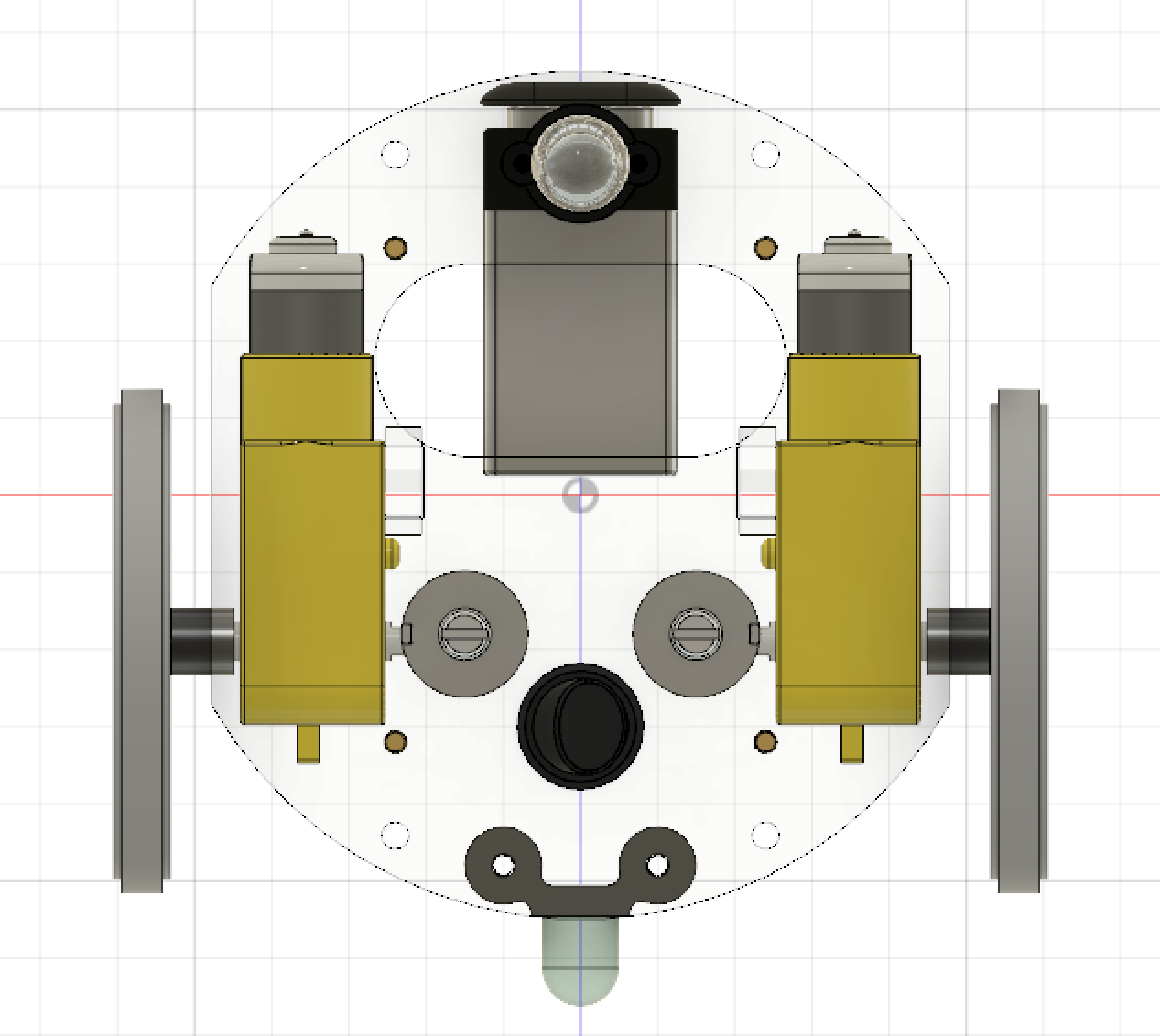
Assembly with the casing removed.
Upon removing the outer casing, the internal structure can be seen in above. Of the two acrylic plates, the one at the top supports the PCB while the other supports the remaining electronics, and will be connected to the outer casing. Standoffs were used to connect the two acrylic platforms to each other while maintaining a gap large enough in between for the motors and electronics to fit.
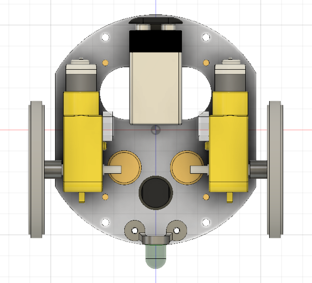
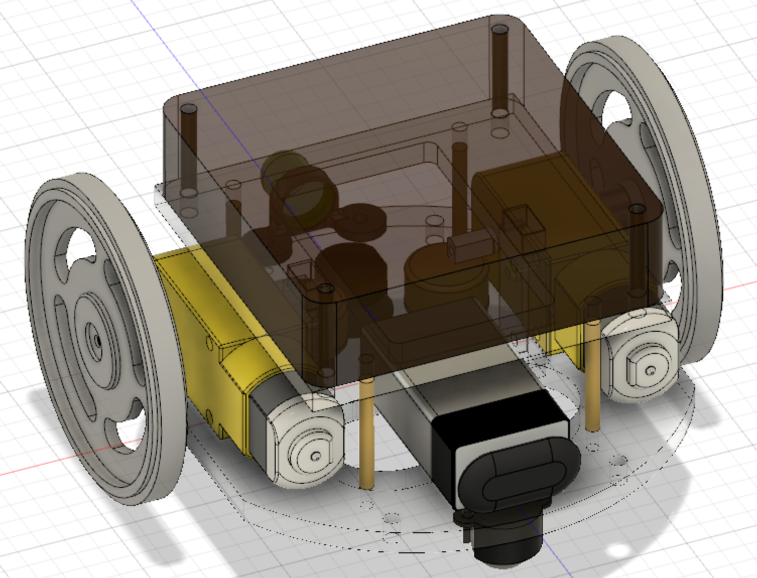
Top view of lower platform.
Bottom view of lower platform.
Finally, removing the upper acrylic platform gives a better look of the electronics mounted to the bottom of the robot. The LED, potentiometers, and power switch are mounted to the bottom acrylic plate to keep them accessible from the outside once the robot is assembled. A slot was cut into the bottom so the user could reach in to remove the battery without disassembling the robot. The four holes seen in above images are through holes for attaching the outer casing to the platform.
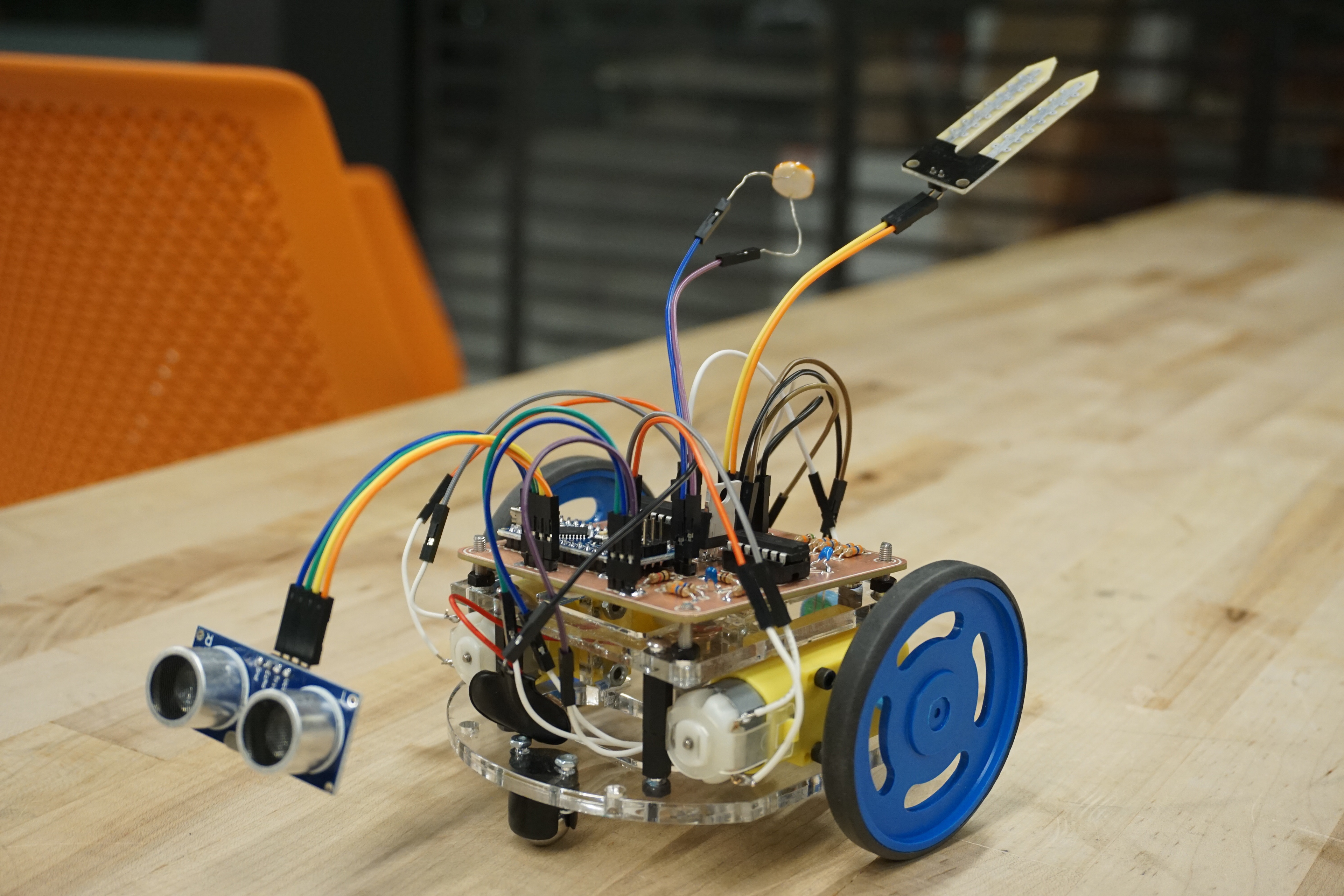
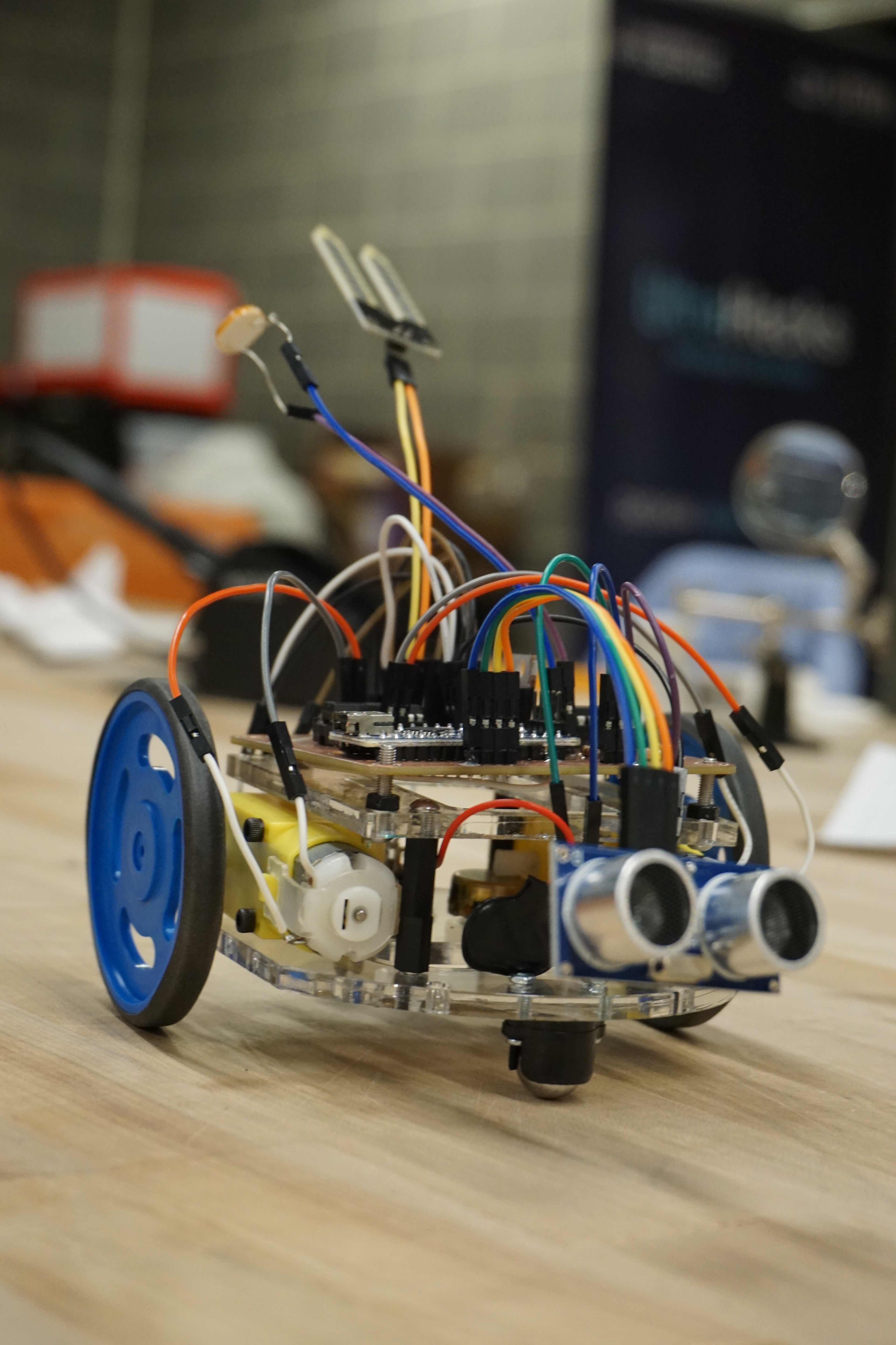
The manufactured chassis can be seen above without the casing.