After some testing in the cardboard chassis, the motors became lose and no longer allowed the robot to move in a straight line. So, I decided to make a skeleton that would reinforce a new chassis.


After measuring and recreating the components in Solidworks, I played around with them to try to find the most compact positioning while still maintaining easy access to the micro controller and batteries. Once I decided on the layout, I designed a frame around it. The model was sliced using CURA and printed using my Monoprice Select Mini V2.
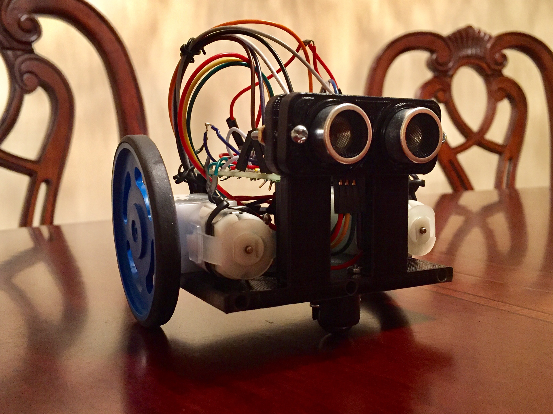

It took a few tries to get the model to print right. This was due to the inconsistent tolerances on my printer. For example, the screw holes close to the ultrasonic sensor were ___ but back ones were ____, both ended up threading the same way. But once I figured those out and updated the model, it was just a matter of printing it, giving it a cool paint job, and installing the electronics.
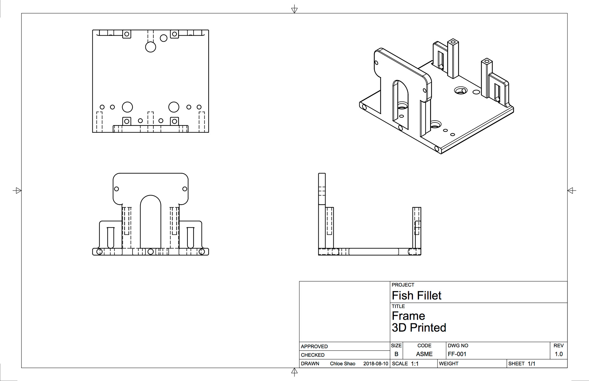
The frame features:
- Stands for screwing the circuit board onto
- Holes for routing wires out of the bottom of the chassis and into the light sensors
- Adjustable mounting wedges for attaching the light sensors
- Holes for twist ties that help keep the motors from moving
- Screw holes for the caster wheel
- Fancy mounting plate for the ultrasonic sensor

Last but not least, the face was completely necessary.