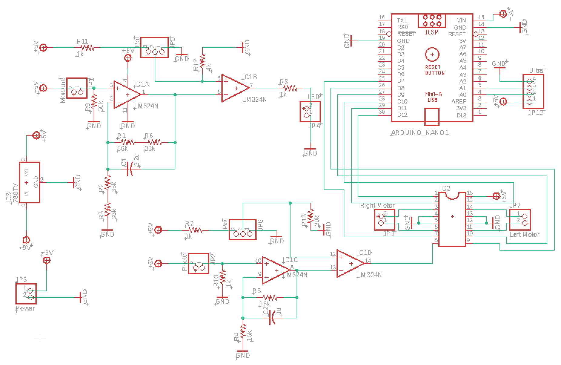
Eagle schematics.
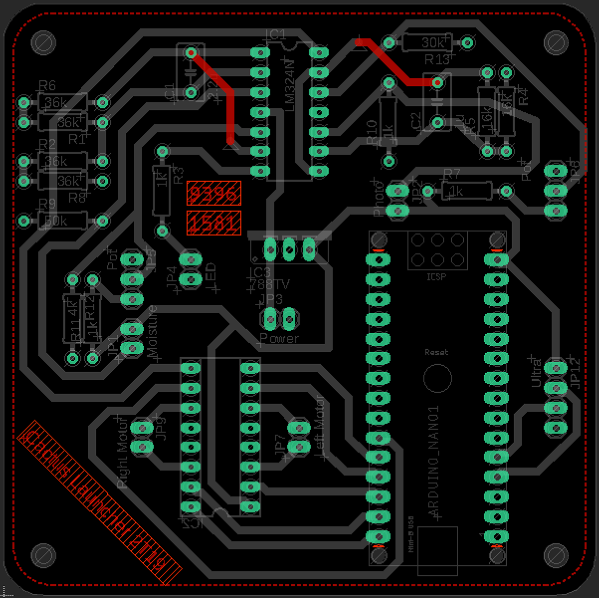
Solder top layer.
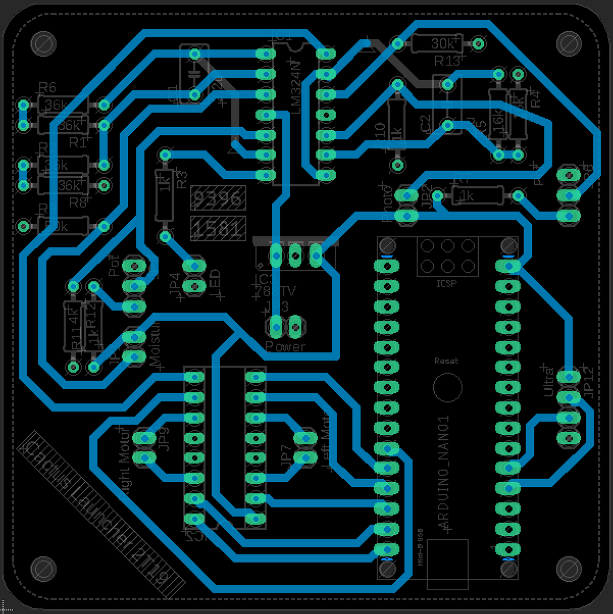
Solder bottom layer.

Silkscreen layer.
As seen above, Eagle was used to lay out the board. A smaller board was designed to test the op-amp part of the circuit but this was not included as the only resistor values were changed. An LM324 chip was used with two op-amps working as low pass filters for the moisture sensor and the light sensor while the other two were used as comparators. The "compared to" value of the comparator could be adjusted using a potentiometer for both sensing circuits. For the moisture sensor, an LED would turn on once the resistance of the sensor decreased the voltage to the compared value. The light sensor used a similar method except it would power the motor driver instead.

Top of soldered board.
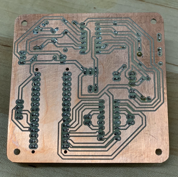
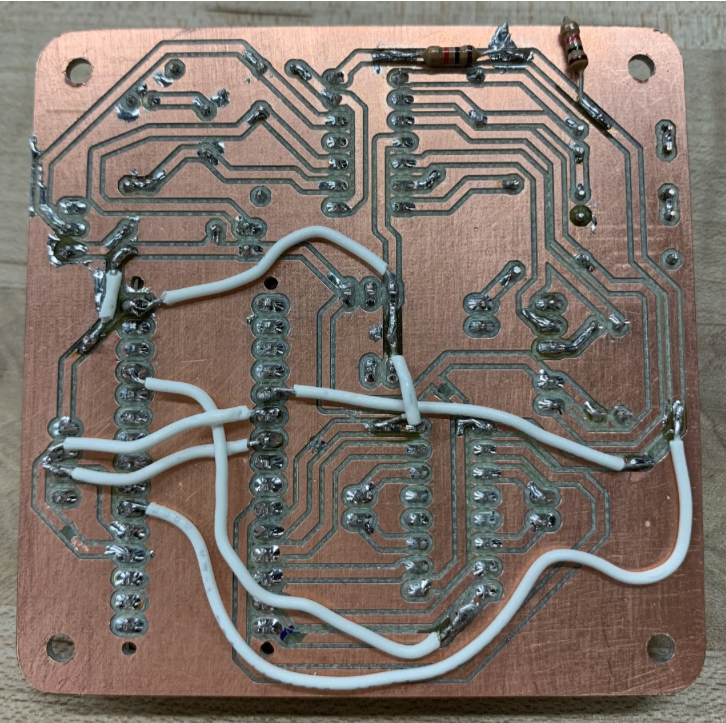
Bottom of soldered board.
Above, the board soldered by Michelle can be seen. Due to the addition of the motor driver and Arduino Nano, the final board did not work as intended and modifications needed to be made.
Bottom of modified board.
Our list of problems and solutions is as follows:
1. Voltage output from the op-amp used to power motors did not provide enough current;
Solution: Use the voltage output from the op-amp to enable the motors instead.
2. Tried the solution mentioned in problem (1), the op-amp was outputting too many volts so the motors would not run;
Solution: Include a voltage divider before the pin.
3. Determined the motor driver was designed for digital signal instead of (unstable) analog input, meaning the solution to problem (2) did not work;
Solution: Rerouted chip power (5V) to nano and output signal to A2, Nano checks signal and powers motors if necessary.
4. Arduino Nano did not receive sufficient power;
Solution: Rerouted Vin to 9V instead of 5V and let the on-board regulator power it.
5. Accidentally wired ultrasonic trig and echo pins to analog pins on the Nano;
Solution: Removed the copper connections on board and used wires to reroute the connections to digital pins.